Stimulus Generation
Stimulus Generation
BonVision has the following solutions for Stimulus Generation:
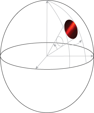
A. Sphere Mapping
This is best for creating 2D stimuli
Note: Needs a Display object: preferably a ViewingWindow
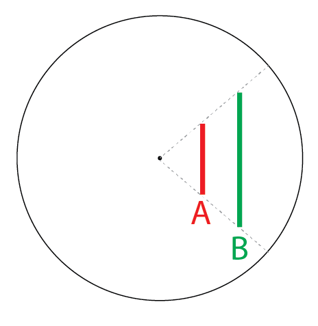
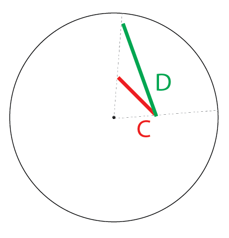
In this case, stimuli are always rendered onto the inside of a sphere. This allows easy eye-centric definitions pf stimuli in visual angle units. The displays are then windows that observe these rendered stimuli. We use Spherical coordinates to define all stimulus parameters in this case.
The details of the implementation of Sphere mapping
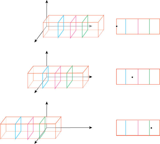
B. Cube Mapping
This is best for creating 3D stimuli, for Virtual or Augmented Reality Systems
Note: Needs a Display object: preferably a PerspectiveViewingWindow
The details of Cube Mapping are explained here:
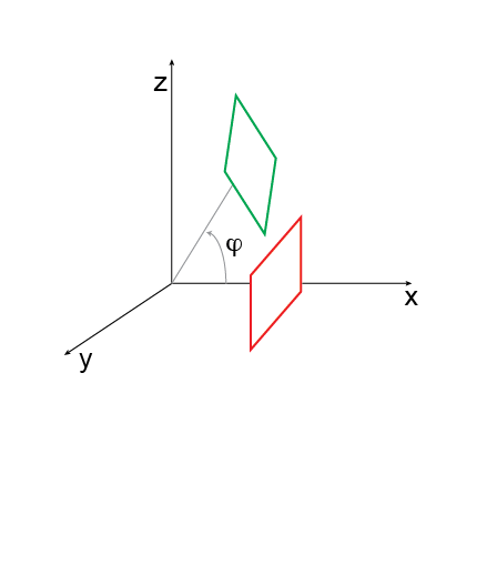
In this case all the stimuli are created in eye-centric physical coordinates (centimeters for example) and rendered onto a unit Cube. The displays (Perspective cameras) are then windows into these rendered images. probably easiest with a whiteboard drawing here
For Virtual Reality (VR)
VR can be easily defined as a situation where the eye, and the screens (windows) are fixed positions, while the all the objects (or VR environment) moves across the eye.
Example rendering to be added here
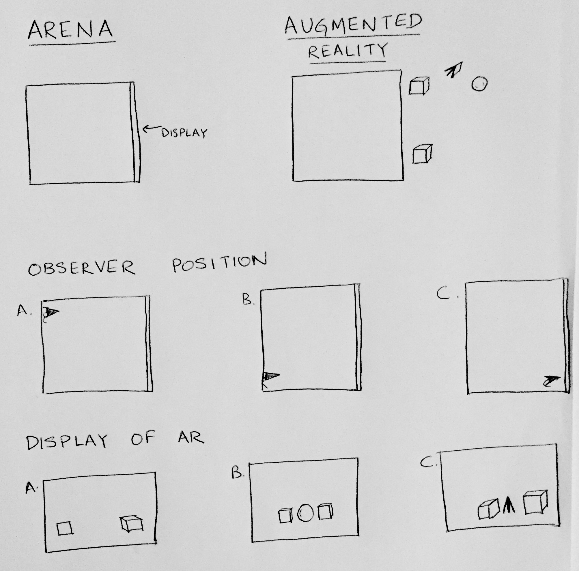
For Augmented Reality (AR)
This is a scenario where, generally, the screens remain in a fixed position and the animal can move around. Since we have an eye-centric coordinate frame, the objects and the screen move around to generate an AR.
Example rendering to be added here
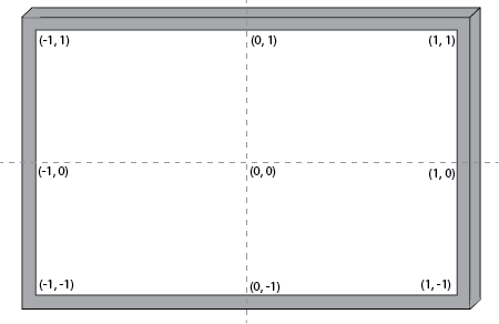
C. Normalized Viewport
This is convenient while designing and testing, prior to an actual experiment
It just scales the screen from -1 to 1 on the two axes
Display Types
BonVision has the following solutions for DisplayTypes:
I. ViewingWindow
This is best for creating 2D stimuli
This is a flat screen defined by 6 measurements (for a complete discription). Multiple display objects can be added by just adding additional ViewingWindows.
These are the measures that need to be added for each display object:
- Distance of left bottom corner (from eye)
- Distance of left top corner (from eye)
- Distance of right top corner (from eye)
- Distance of right bottom corner (from eye)
- Azimuth (horizontal angle from straight ahead) of the centre of the display
- Elevation (vertical angle from horizon) of the centre of the display
This is an example of the same stimulus rendered on different displays:
Images on A, B and C
II. PerspectiveViewingWindow
This is best for creating 3D VR/AR stimuli
III. MeshMapping
When using a projector in conjunction with a mirror or lens
Lens or mirrors cause distortions in the image, such that pixels across the display surface might not have the same physical dimensions. In this case, one would have to measure the distortions and use these to warp the images to display them correctly. In the case of 3D worlds, they might be best use in conjunction with multiple PerspectiveViewingWindows looking at different parts of the world.
IV. GammaCorrection
When using a projector in conjunction with a mirror or lens
This is simple intensity mapping of the three colors, to make sure the stimuli are linear. It uses a simple LUT (Look-up-table), for Red, Green and Blue.